CHAPTER VI SEDIMENTOLOGICAL ANALYSIS OF THE DEPOSITS IN THE DOUARA CAVE SITE
Kunihiko ENDO
Department of Geography, Faculty of Science, The University of Tokyo
|
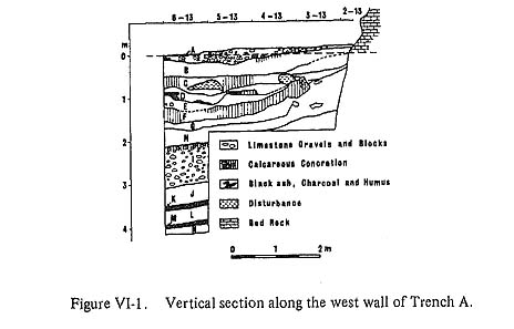
In Chapter II the general features of the deposits in the Douara Cave Site were described, Field observation during the 1970 season clarified various features of the deposits, for example, their distribution, color, texture, hardness, compactness, stickiness, stratification, and humus content, and the nature of the calcareous concretions. Laboratory work provided further data through grain-size analysis, chemical analysis, mineral analysis, X-ray analysis and so on. In this chapter, these observations and analytical data are used to attempt a reconstruction of the sedimentary environments and climatic conditions during the periods of deposition seen in the cave. 1. THE DEPOSITS OF THE DOUARA CAVE SITEThe deposits of the Douara Cave Site are divided into 14 layers, designated Layers A to N, based mainly on the color and texture of the deposits, as noted in chapter II. Figures VI-1 and VI-2 show vertical sections through the deposits along the west wall of Trench A and the north wall of Trench B respectively. Layers A and B are occupational layers of the Upper Palaeolithic, and C, D and E are occupational layers of the Middle Palaeolithic. These five layers all contain large quantities of flint implements and animal bones, and their sedimentation was greatly influenced by human habitation. Layers F to I contain only a very few flint implements and were only slightly influenced by human habitation. Layers J to N contain no artifacts or animal bones and seem to be without any influence from human habitation. The various properties of each layer were elucidated mainly through field observation. These properties are as follows.
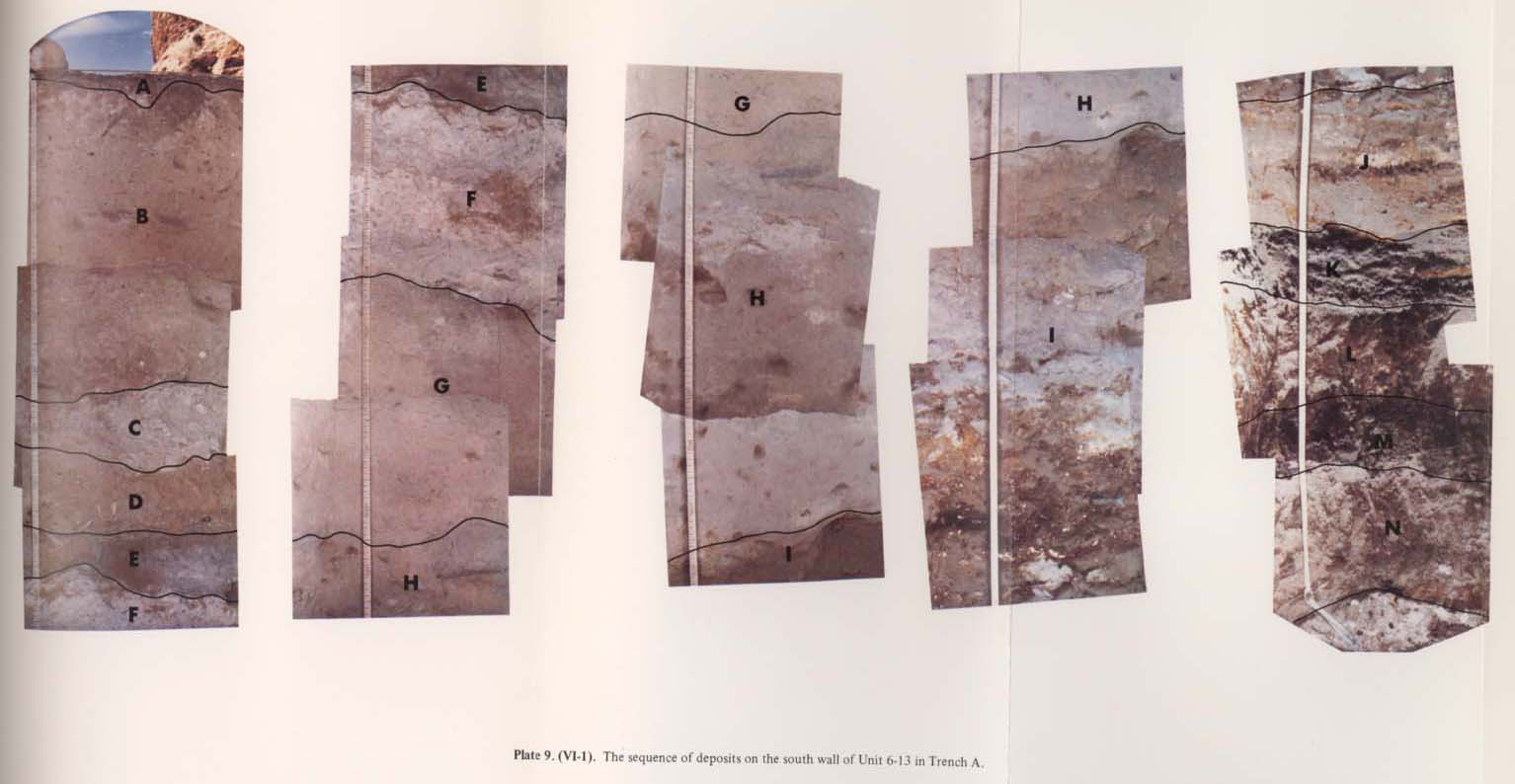
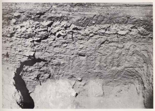
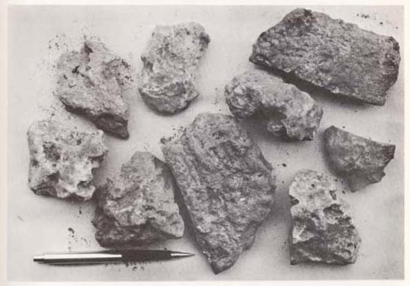
1) ColorLayers A to I are grayish colored as a whole. On the other hand Layers J to N are variously colored in browns, reds and black (Pl, VI-1). Of the occupational layers, Layer A is yellowish gray, Layers B and D are light brown to grayish brown, and Layer E is gray to grayish brown. Layers C and F are composed of calcareous concretions and are white to whitish gray. The colors of Layers E and D are variable because of the frequent occurrence of thin, black or whitish colored bands interbedded intermittently in them. Layer G is a unique pinkish color. Layers H and I are deep brown to yellowish brown, and become deeper in color toward the base. The non-occupational Layers J, L and N are yellowish brown to reddish brown, but the color is homogeneous in each layer. These seem to be soils that were weathered for a long time. Layers K and M are black soils with an abundant admixture of humus.
2) Limestone RubbleLayers A and I are rubble layers containing about 30 percent rubble as their principal component (Fig. VI-4). Except for these two layers, limestone rubble occurs only sporadically. Almost all the rubble is limestone, but some of it is fragments of flint and calcareous concretions. The limestone rubble might have been accumulated as rock falls caused by mechanical disintegration of the limestone forming the ceiling and walls of the cave.
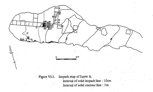
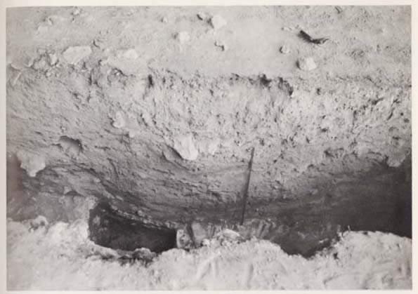
Limestone rubble generally accumulated where it falls unless the slope is so steep that it rolls and slides downhill (Cornwall, 1958), or unless running water entering through fissures transports it downwards. No evidence was found in the deposits of the Douara Cave to indicate the transportation of the rubble by water. The two rubble layers differ each other in sedimentary character. Layer A: This rubble layer is distributed only in the area outward from Unit 7-10 in Trench B(l), and it fills up a depression crossing Unit 7-11, also in Trench B. This depression, reaching 100 cm at maximum depth, seems to be an extention of the shallow depression crossing Trench A (Fig. VI-3, Pl. VI-2). The Origin of the depression is important when considering the sedimentary environment of this rubble layer, but we must await further excavation to solve this problem. The Layer A rubble (Pl. VI-3a) is fresh and angular and lacks uniform orientation. Its size ranges from pebble to boulder but is mainly pebble. Its maximum size is about 30 cm in diameter. The sorting of the rubble is poor, and its shapes are not uniform.
One fact to be considered in regard to the formation of Layer A, is a large fallen rock lying in the center of the floor at the cave entrance (Fig. II-4). No curtains of recrystallized calcium carbonate, a sort of flowstone or dripstone, are formed on the surface of the cave ceiling just inside the edge of the cave roof from where rock falls might have occured on large scale. However, the relationship between the large rock fall and Layer A cannot be discussed directly because the area under the rock fall was not excavated. But it can be discussed indirectly from the sequences in Units 7-14 and 7-17 which about both sides of the rock fall.
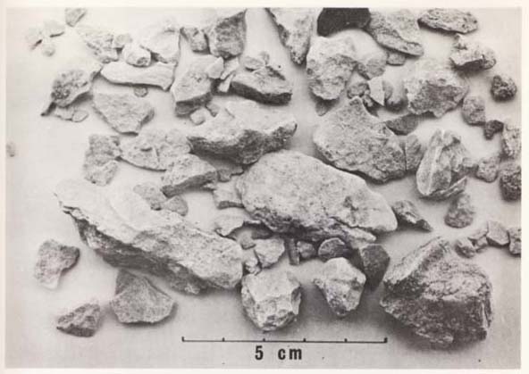
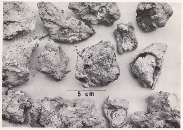
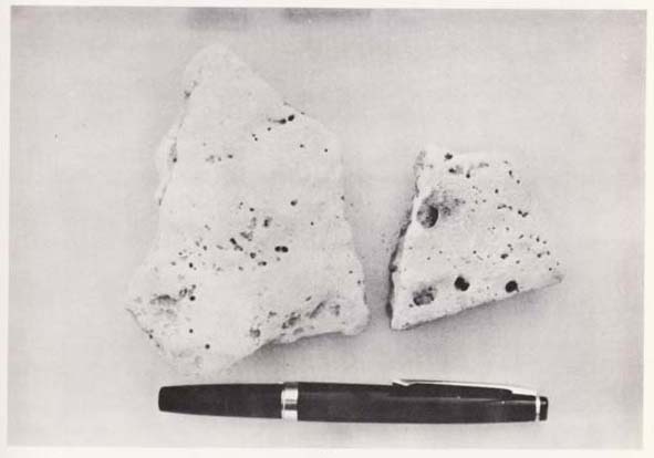
The sequence in Unit 7-14 is shown in Figure VI-2. Layers A to F were excavated here. In the outer half of the unit, the whitish concretion of Layer C fades away and the boundary between Layer B and Layer C becomes obscure. In Unit 7-17, Layers D, E and F were clearly recognizable. The deposit overlying Layer D is apparently divided into two layers, an upper layer composed of limestone rubble and blocks without matrix materials and a lower layer composed of grayish brown, silty sand. Around Units 7-17 and 7-18 outside the dripline of the cave, it is thought that a great amount of limestone rubble and blocks fell directly from the slope above the cave and accumulated before the entrance. Moreover, fine materials on the top layer tend to be transported downwards by water running down from the mountain slope. Consequently, the top layer outside the dripline is different in character from the one inside, making it fairly difficlut to correlate them. The stratigraphical correlation of the upper layer, which includes no artifacts, is a problem for future study. But the lower layer is similar to Layers B and C in the outer half of Unit 7-14 inside the entrance. The large fallen rock appears to correlate with the upper layer in Unit 7-17, and it seems possible, then, that it overlies Layer B. This indicates the possibility that the rock fell simultaneously with the deposition of Layer A. Though further studies are required to clarify this correlation, at the present stage it is not necessary to conjecture that the accumulation of the limestone debris caused by climatic change (colder or wetter conditions). Around the Douara Cave, a great number of joints, small faults and fissures were found in the limestone (Chapter II). Moreover, active faults cutting the younger wadi fan surfaces were found in the vicinity of the cave. It might represent large rock falls caused by such accidents as tectonic movements. Layer I: The characteristics of the Limestone rubble in Layer I are different from those of Layer A in several ways (Pl. VI-1). The total thickness of Layer I was observed only in Unit 6-13; there it was 65 to 90 cm. Layer I seems to be distributed throughout the cave and is at least 20 cm thick as shown in Figure VI-2. The Limestone rubble is angular and flat in shape and mainly of cobble size, and its variation in size and shape is less than for the rubble from Layer A (Pl. VI-3b). The Layer I rubble is highly weathered, and brownish colored crusts have been formed on the surfaces of all pieces. This is a distinct contrast with Layer A where the limestone rubble is fresh. Layer I is considerably hardened and compacted with a sticky matrix composed mainly of fine sand and silt. Each piece of the rubble lies generally with its flat surfaces horizontal. The most noticeable feature of Layer I is the occurence of some thin beds composed of a calcareous concretion intercalated intermittently in the uppermost horizon of the layer. Limestone debris and a great quantity of animal bone fragments are cemented tightly with recrystallized calcareous materials in these concretion beds.
As described later, the uniformity throughout the cave of the various characteristics of Layer I, and especially the occurrence of the intercalations of calcareous concretions, suggest the probability that the limestone rubble of this layer was accumulated under colder or wetter conditions than those of Layer A. 3) Calcareous ConcretionsThe calcareous concretions found in the cave deposits can be divided into four types, three of them typified in Layers E, F and I. The fourth is the wedge-shaped type developed in the deposits near the cave wall. These concretions are regarded as sorts of dripstone or flowstone. Butzer (1971) pointed out that in arid and semiarid regions, caves without modern dripstone formation will produce such features only with an increase of moisture. As Cornwall (1958) also noted, the intercalation of a dripstone floor in a cave section should be interpreted as the result of a period of wetter conditions in the Mediterranean region and its vicinity. The first type, found in Layer E, consists of lenses of a whitish calcareous concretion usually accompanied by black colored lenses of humus or powdered charcoal (Pl. VI-4). Calcareous concretion lenses of this type are 10 to 70 cm in length and 2 to 10 cm thick and not as hard as concretions of the other types. They are composed of materials of fine sand and silt size. This type is abundant in the inner units of Trench B. Thick alternation of concretion beds of this type are observed in particular in Layer E in Units 7-4 and 7-5 adjacent to the hearth layer in Unit 7-3. This first type of the concretion is also found abundantly in Layer D.
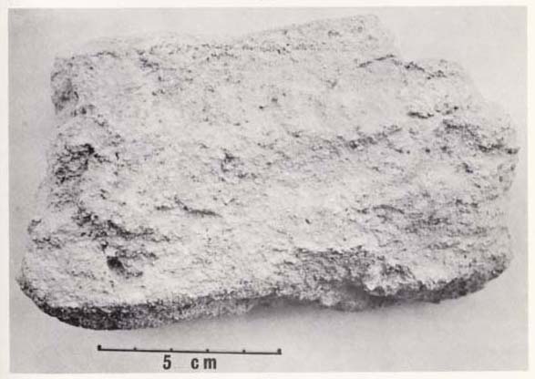
Layers D and E are the layers most influenced by human activity, as is suggested by the abundant occurrence of charcoal or ash lenses, flint implements and animal bone fragments. The relationship between the formation of concretion lenses and human activity cannot be ignored, but whatever this relationship, it seems reasonable to say that transportation and precipitation of calcium carbonate by dripping or flowing water probably occured actively during the period of deposition of these layers. A few lenses of concretions of this type are found also in Layers H, J and B. The second type is a massive, relatively homogeneous calcareous concretion. Layers F and C themselves are formed almost entirely of the concretion of this type (Pls. VI-1, 2 and 5). The concretion is whitish colored and contains as its principal component fine materials composed mainly of silty sand plus a fair amount of pebble-sized limestone debris. It is too hard to excavate using a trowel, but it is not as hard as the type found in Layer I. It can be reduced to the original grains and particles by placing it in water and crushing it with the finger, but the calcareous concretions in Layer I cannot be reduced in this manner.
Layer F is extremely thick as compared to the other concretion layers, and is distributed continuously throughout the excavation area. It includes a few artifacts and animal bones. The boundary between Layer F and the overlying layer is very clear and considerably undulating. The boundary between it and the underlying layer is relatively smooth and transitional in some places. There are the clear differences in texture, chemical composition and other sedimentary characteristics between Layers F and G. These suggest that the calcareous concretion of Layer F was formed by the precipitation of calcium carbonate from permeating calciferous water spreading out in sheets simultaneously with or Just after the deposition of Layer P. The transportation of calcium carbonate appears to have been most active during the deposition of Layer F. The concretion of Layer C thinly covers the slope and bottom of a depression (Pl. VI-2), It includes the largest number of flint implements per unit of volume. These flint implements have the same manufacturing technique as those of Layer D and are discolored and broken with the tight adhesion of the calcareous concretions. Layer C is probably the sediments associated with the formation of the depression which was eroded into Layer D. Further, it is likely that the flint implements and other components in Layer C were derived from Layer D. The calcareous concretions of Layer C may have been formed by water flowing down along the depression. The third type, found in the upper part of Layer I, is an interbedding of a few thin layers of exceedingly hard calcareous concretions. Each layer is about 5 cm thick and includes a larger quantity of limestone debris and animal bones, than the surrounding rubble bed. The limestone debris and animal bones are cemented compactly by amorphous or mostly recrystallized calcium carbonates (Pl. VI-6a). It is too hard to dig without using a hammer. This type can be called a sort of cave breccia. It is probably distributed throughout the excavation area. At least, during the last stage of Layer I, the cave was subjected to remarkably wet conditions, and breccia type concretions were probably formed by calciferous water which spread out in sheets and permeated the uppermost part of the rubble layer.
The wedge-shaped fourth type was found in the wall-side deposits of the cave, especially in Trench A. It extends from 10 to more than 100 cm from the cave wall, extending wider with depth in a wedge-like shape. It was formed by calciferous water which trickled down through walls and fissures to reach the floor and permeated into the deposits. Owing to these latter concretions, excavation and the division of the deposits near the cave wall were very difficult. 4) Hardness, Compactness and StickinessLayers C, F and I, which include hard calcareous concretions, register the highest in hardness and compactness. Except for these layers, the deeper the layer is the greater its degree of hardness, compactness and Stickiness becomes. This is especially so below Layer H. Layers A to G are less sticky, parched, ash-like sediments, but Layers H to N are sticky and more or less damp sediments (Table VI-1).
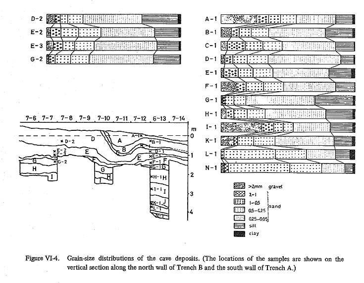
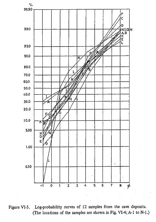
2. GRAIN-SIZE DISTRIBUTIONS OF THE CAVE DEPOSITS AND THEIR CORRELATION WITH THOSE OF DEPOSITS AROUND THE CAVESixteen samples from 12 layers (samples were not selected from Layers J and M) were collected for grain-size analysis of the cave deposits. These samples were taken from the north wall of Unit 7-12, the west wall of Unit 6-13 and the north wall of Unit 7-7 (Fig. VI-4). The size grades used in this analysis are > 2 mm, 2-1 mm, 1-0.5 mm, 0.5-0.25 mm, 0.25-0.05 mm, 0.05-0.002 mm and < 0.002 mm. Analysis of the coarse fraction was made by dry sieving, and the fine fraction by the pipette method. The results are shown in Figure VI-4 and Figure VI-5.
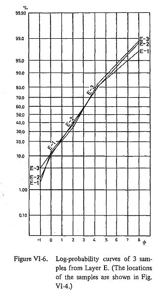
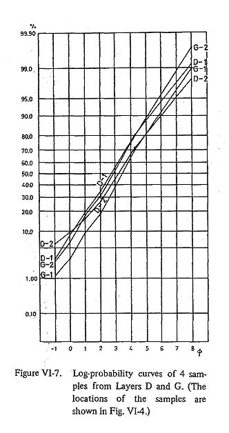
The layers fall into 3 categories according to their predominant grain size. The first category includes Layers B to H and K. Their main constituents are fine sand and silt size materials. The second category includes Layers A and I. Their main constituent is rubble. And the third category includes Layers L and N whose main constituent is medium-grained sand. The Log-probability curves in Figure VI-5 present graphically the differences in these three categories of grain-size distribution. The samples in the first category are 50 to 80 % and average 60 % fine materials graded less than 0.25 mm. In detail, the very fine sand-and coarse silt-size fractions are the most predominant as shown in the size frequency distribution curves 7 and 8 in Figure VI-8. There are two subcategories in this cagetory. One is typified by Layers F and C which are calcareous concretion layers and are relatively rich in coarse materials, and the other is typified by Layer G which contains an especially large proportion of fine sand and silt-size materials. The grain-size distribution of the second category is similar to the first category above but contains a much large proportion of gravel-size materials. The third category has distinctive characters as shown in Figure VI-5, and the deposits are likely wind-laid or fluvial. A fair amount of the sand grains is rounded quartz as described later. The source of the quartz can not be expected in the mountains behind the cave, and moreover, there is no indication of transportaiton by water at the time of deposition of Layers L and N. Result of the analysis shows that the sandgrains are much larger than ordinary wind-blown sands. However the quartz grains are coated thickly by fine materials such as clay minerals, and the grain size obtained by the analysis is larger than original size. Variations in grain-size distributions within one layer are shown in Figure VI-6 for Layer E and in Figure VI-7 for Layers D and G. The three curves for Layer E show a uniformity of size distribution throughout the layer. The curves for Layers D and G show a small deviation in grain-size although the size is roughly constant throughout the cave.
The grain-size distributions of various deposits around the cave for the wadi fan surface (2), the wadi floor, the basement of the wadi fan gravel beds, the aeolian sands of the Nebka zone (2), the surface and subsurface deposits of the Sabha (2), salt marsh, as well as for the cave deposits (Layers D and E), are shown in Figure VI-8 (3). Only the subsurface sample of Sabha and the cave deposits are characterized by a major proportion of very fine sand or coarse silt. The other samples are classified into two types, one composed mainly of sand size materials and the other of admixture of gravel-sized and sand-or silt-sized materials.
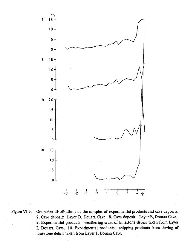
A great amount of limestone rubble is contained in Layer I. The procedure of the grain-size analysis for materials produced experimentally from the limestone rubble is as follows. The brown weathered crusts on several cobble-size pieces were removed by brushing in water. The grains and particles so removed were dried and separated by sieving at 1/4 φ intervals. Three of the cleansed pieces of rubble (Pl. VI-6b) were gyrated for about 80 minutes in the mesh of a ro-tap sieving machine. The materials produced by this treatment were sieved at 1/4φ mesh intervals. The grain-size distribution of the materials obtained by this cleansing and grinding are graphically compared in Figure VI-9 to the distributions for the cave deposits. Although the treatment does not necessarily reproduce the natural processes of weathering that took place in the cave, the results suggest that a great amount of the fine material in the cave deposits might have been produced by the processes of chemical weathering and/or mechanical crushing right in the cave.
3. CHEMICAL COMPOSITION OF THE CAVE DEPOSITSThe chemical composition of the cave deposits was analyzed by the Japan Analytical Chemical Research Institute. One sample each from Layers B, F and G (samples B-1, F-1 and G-1 respectively) were selected for this analysis. The results are given in Table VI-2, and the locations of the samples are shown in Figure VI-4. It is evident from Table VI-2 that the principal constituents of these samples are CaO, CO2 and SiO2. The estimated calcium carbonate (CaCO3) contents are about 55 % for sample B-1, about 75 % for sample F-1 and about 30 % for sample G-1. Sample B-1 is relatively rich in SiO2. Sample G-1 relatively poor in CaCO3, is richest in SiO2. It also includes considerable amounts of Al2O3 and Pe2O3, plus CaO not combined with CO2 to form CaCO3.
An estimate of the relative content of calcium carbonate in the cave and surrounding deposits was made by measuring the total loss of solubles (by weight) after submergence of a sample in 10% hydrochloric acid. The results are shown in Table VI-3 and Table VI-4. The twelve cave samples used here are the same samples A-1 to N-1 used in the grain-size analysis, and their locations are shown in Figure VI-4. This analysis was done mainly for the fine sand fraction. Several tests were run of other fractions to verify the results.
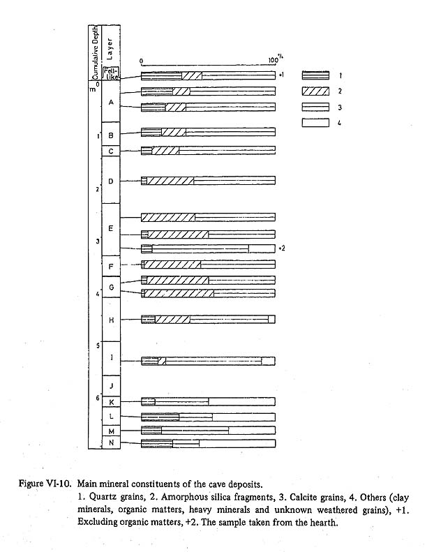
The CaCO3 values obtained from the measurement of the amount of HCl-solubles is thought to exceed the true calcium carbonate content to some degree. The measured values for samples B-1 and F-1 as shown in Table VI-3 are about 1.2 to 1.3 times as much as their estimated values obtained by chemical analysis (Table VI-2). For sample G-l the measured value in Table VI-3 is 1.8 times the estimated value given in Table VI-2. This deviation is due partly to the increased SiO2 content in the coarser fractions as discussed later. Table VI-3 shows clearly the small quantity of HCl-solubles in Layers K, L and N, This is probably due to the richness of clay minerals and quartz grains in these layers, as is discussed in more detail below. Contrarily, the amount of HCl-solubles included in Layers A to I exceeds roughly 70%, and in Layers A, C and F it exceeds 80%. The calcareous concretions in Layers C and F account for their high values. The greater portion of each sample from the deposits around the cave is soluble in HCl. Only the aeolian deposit from Rejm el Qili (4) near exposed flint beds is largely insoluble. The two powdered samples of the limestone bedrock around the cave are 100 % soluble. The insoluble residue from the weathering crusts of the limestone rubble from Layer I is thought to be chiefly clay minerals. It is necessary for the interpretation of the results of chemical analysis that the mineral composition, especially the SiO2 constituent, is clarified. This is discussed in the following section. 4. MINERAL COMPOSITION OF THE CAVE DEPOSITSThe mineral composition of the cave deposits was analyzed in order to clarify the parent material from which the cave deposits were derived and to discuss the sedimentary environment. This analysis was done chiefly for the fine sand fraction of the eighteen samples (fifteen samples shown in Figure VI-4, plus three samples from the lower horizon of Layer A in Unit 7-11, from Layer M in Unit 6-13, and from the felt-like surface layer) shown in Figure VI-10. The fine sand fraction was selected because it is the principal component of most of the layers, and also because of its convenience of treatment. This fraction was separated from the other fractions in the process of the grain-size analysis. Grains or particles unidentifiable under the microscope were determined by means of X-ray analysis. The principal mineral components of the fine sand fractions are calcite grains, quartz grains and amorphous silica fragments. There are also a small amounts of heavy minerals and clay minerals, such as hematite, pyroxene, gibbsite, kaolinite and montmorillonite.
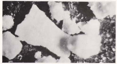
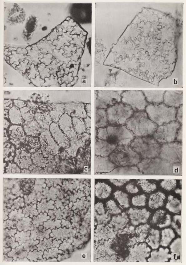
1) Calcite GrainsThese can be confirmed by submerging them in 10 % HCl under the microscope. These grains are typically angular, opaque and white colored under reflective light (Pl. VI-7a). The surfaces of the grains are rugged, and some of them are covered with fine spinous calcite. There are also recrystallized foraminifers among the calcite grains. These are rounded and partly transparent.
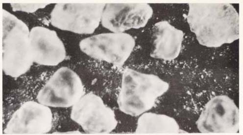
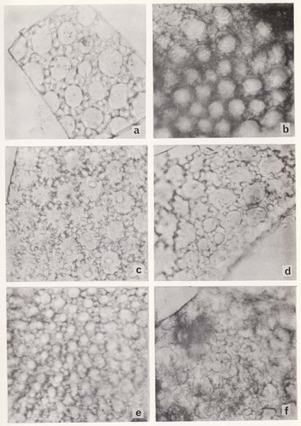
Calcite grains make up generally from 30 to 80 % of the total grains (Fig. VI-10). The proportion of calcite grains contained in each sample varies in accordance with that of CaCO3 contents obtained by chemical analysis. A great number of foraminiferal tests are contained in the felt-like layer which covers the surface of the cave floor. These are poorly preserved and are recrystallized. The following foraminiferal genera (5) were identified in this layer: 1) Woodringina? sp., 2) Globorotalia sp. indet., 3) Globigerina spp. indet., and 4) Uvigerina spp. indet.. According to Prof. Takayanagi, the composition suggests derivation from Paleocene deposits. The main source of foraminifers in this layer is probably the Paleogene limestone beds forming the cave ceiling and walls. Layer A contains only a small number of foraminifers (about 5 % of the total grains) which are more poorly preserved than those in the felt-like surface layer. The layers below Layer A contain very few foraminifers. On the other hand, a great number of recrystallized and poorly preserved foraminiferal tests are contained in the sandy deposits of the Sabha marshland and Nebka zone. These are planktonic foraminifers (6) such as 1) Rugoglobigerina rotunda Bronnimann, 2) Globigerina cf. tripartita Koch., 3) Pseudoguenibelina sp.,4')Heterohelix sp.,and 5) Globigerina spp. indet.. It is unlikely that the foraminifers and other calcite grains in the cave deposits were blown in from the Sabha because the foraminiferal species in these two locations are different. But it is probable that they were blown into the cave from the surface deposits around the cave, for example, from the wadi floors near the cave (Pl. II-3a) - Paleogene deposits are exposed in Jebel ed Douara in the upstream areas of these small wadis. 2) Quartz GrainsThe majority of quartz grains are well rounded and spherical in shape (PI. VI-7b). In general, they have clean, smooth surfaces without adhesions of cementing materials, except for the samples from Layers L and N, The quartz grains in these two layers, especially in Layer N, are thickly coated with brown colored materials. Quartz grains make up 15 to 30 % of the samples from Layers A, B, I and N, but less than 5 % of the samples from Layers D, E, F and G (Fig. VI-10), The felt-like surface layer also is rich in rounded quartz grains.
Quartz grains are not contained in the Paleogene limestone beds around the cave (Table VI-4). On the other hand, other deposits (such as the surface deposits of Sabha central marsh, the aeolian sands of Nebka, the wadi fan deposits and the basement sediments of the wadi fan gravel) contain considerable proportions of quartz grains. These grains are well rounded and mainly of fineto medium-sand size. Consequently, the source of the quartz grains contained in the cave deposits is probably these surface deposits, especially those around the cave. Cailleux (1942) studied on the morphological properties of quartz sand grains and evaluated them quantitatively as indices of periglacial conditions in the Pleistocene of Western Europe. Rust (1950) regarded rounded quartz grains found in the lower deposits of Yabrud Shelter I as one of the evidences of dry conditions. In the Palmyra Basin, there are recent evidences to show active transportation of sand and dust by wind - the Nebka sand mounds and the sand pillars which occur frequently in the dry season. Large numbers of quartz grains are contained in the felt-like surface layer of the Douara Cave. This layer is a recent deposit. These data suggest that present conditions are favorable for wind transportation of quartz grains, and that the quantity of rounded quartz grains in the deposit can be used as an index of the intensity of wind transportation or dry conditions. However, this rests on the supposition that there was a constant source of quartz grains available for transportation in the past. Quartz grains are common in the sandy deposits of the Sabha surface (Pl. VI-8a), the younger wadi fan deposits that roughly corresponded to Middle and Upper Paleolithic (7), older wadi fan deposits predating the Middle Paleolithic (7), the sandy formations underlying the wadi fan gravel beds (Pl. VI-8b), and the Neogene sandstone exposed around Wadi el Ahmar. In the vicinity of the cave, quartz grains also are commonly contained in the wadi fan deposits, and are especially abundant in the lower horizons. The source of quartz grains in the past seems to have been existed uniformly or gradually decreasing. Considering that active wind transportation of sand grains is observed under the present dry conditions, it seems reasonable to assume the variations in the proportions of quartz grains reflect changes in relative moisture.
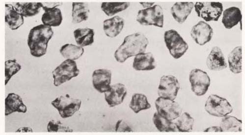
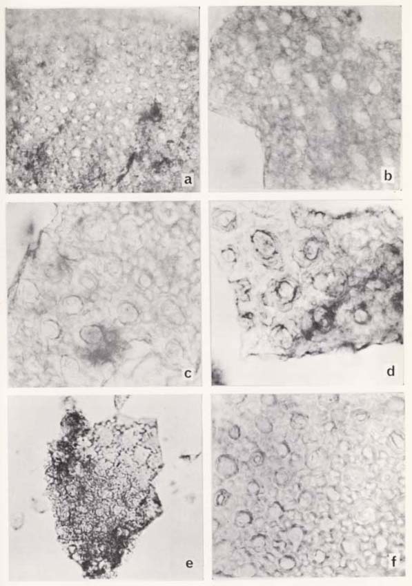
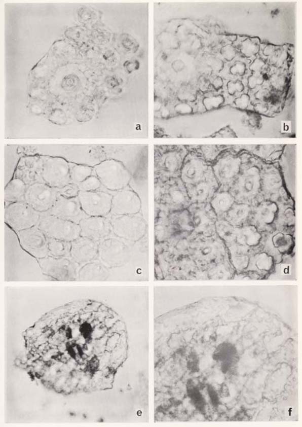
3) Amorphous Silica FragmentsFlat, porous fragments are contained in the samples from Layers A through I. These fragments have slightly curved surfaces, and the layer of spongy structure adhering to the outer compact shell is visible under reflective light (Pl. VI-8c). Under the microscope, various structures are observed on the surface of these fragments (Pls. VIII-1~5). This is described in detail in Chapter VIII. Some of these are similar to the characteristic structures seen of plant epidermis. Almost all these fragments are white, but some are brownish or dark colored. These fragments are not soluble in acid or alkali. X-ray powder analysis shows they have the characteristic features of amorphous silica (Fig. VI-11). The origin of these amorphous silica fragments is uncertain (Chapter VIII).
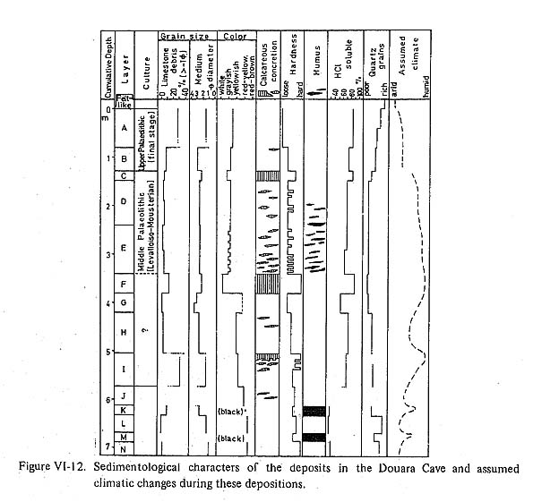
They are found only in the layers containing flint implements and animal bones, but are absent in the sample from the hearth in Layer E. These fragments are most abundant in Layer G and high quantities are found also in Layers D, E and F. Only small amounts of these fragments are found in Layers A, B and C, Layers H and I, and the felt-like surface layer (Fig. VI-10). The silt and medium to coarse sand fractions also were checked for amorphous silica fragments. High proportions of silica fragments were observed in all fractions of the samples from Layers D, E, F and G. In the medium and coarse sand fractions of the samples from Layers F and G, the silica fragments make up as much as 40 to 50 % of the total. This high proportion of the silica fragments accounts for the decreased value for acid solubles in the medium and coarse sand fractions of the sample from Layer F (Table VI-3). The proportions of amorphous silica fragments in the fine sand fractions of the samples from Layers D through G (which contain very few quartz grains) nearly equal the amount of acid insolubles. 5. DISCUSSION OF THE SEDIMENTARY ENVIRONMENTS AND CLIMATIC RECONSTRUCTIONThe constituents of the deposits in the Douara Cave are classified into nine types 1) fine sand and silt size materials composed mostly of calcium carbonate, 2) gravel-sized limestone debris (limestone rubble), 3) sand-sized quartz grains, 4) amorphous silica fragments, 5) clay minerals, 6) organic matter, 7) animal bones, 8) flint artifacts and 9) calcareous concretions. The origins and the processes of deposition of these constituents were discussed individually in the preceding sections. They can be summarized into the following categories: All layers do not necessarily contain the same proportions of constituents from each origin-depositional category. The proportions depend on the sedimentary environment and climatic conditions of the given layer. Some studies have attempted climatic reconstruction through sedimentological analysis of cave deposits in the Levant (Ewing, 1947; Rust, 1950; Wright. 1951, 1960, 1962; Farrand, 1965; Goldberg, 1968; Schroeder, 1969; Chinzei, 1970; and others). Farrand (1965) investigated the palaeoenvironment of the deposits in Yabrud Shelter I. He used such sedimentary characters as color, consistency, calcareous concretions and other data as indicators of palaeoenvironment, Goldberg (1968) carried out sedimentological analyses on the deposits of the Jerf Ajla Site and Yabrud Shelter I. He used the results of granulometry and calchnetry, the natures of calcareous concretions and the shape of the rubble and so on as indicators of climatic conditions. The sedimentological data which are considered the most useful for the reconstruction of the paleoenvironment of the Douara Cave are calcareous concretions, rounded quartz grains, limestone rubble and color. 1) Calcareous ConcretionsCalcareous concretions are formed under wetter conditions than the present and are evidence of humidity. Under the wettest conditions, thick concretion layers or cave breccia are formed by water flowing in sheets and permeating the uppermost horizons of the deposits. Under the less moist conditions, thin layers or lenses of concretions are formed by dripping or flowing water. 2) Rounded Quartz GrainsLarge values for the content of quartz grains probably indicate dry conditions. Small values indicate wetter conditions. However, this assumes a uniform supply of quartz grains. Especially samll values can be caused by a decrease in the supply. But, at the Douara Cave, these values can be assumed to indicate changes in relative aridity because fair amounts of quartz grains are contained in both younger and older deposits distributed widely in the surrounding area. 3) Limestone RubbleFor the climatic interpretation of Yabrud Rock Shelter I, Farrand (1965) adopted the hypothesis of Bonifay (1962) that the coarser the debris is, the colder was the temperature. In this region where recent tectonic movements, such as active faults, are found as noted in the preceding section, application of this hypothesis must be made carefully. When a climatic change is suggested by other factors, a rubble layer is regarded as the result of active disintegration of the limestone under cooler conditions as discussed by Fukuda in detail (Chapter V). 4) ColorAs Farrand (1965) noted, deeply red or yellow colored deposits indicate intensive oxidation in generally warmer temperatures. The reconstruction of the palaeoclimate of the Douara Cave based on the data available at present is summarized as follows (Fig. VI-12):
Of the humid stages noted above, the times of Layers K, F and E correspond to the stages cooler and less drier than the present, assumed by Sohma and Sasaki based on the results of pollen analysis (Chapter IX). Sohma and Sasaki also assumed that in the time of Layer A dry steppe vegetation was existed. Figure VI-13 shows the climatic interpretation of three Palaeolithic Sites in Syria. The interpretation is based on the sedimentological analyses of the deposits. These three sites are now under the dry conditions and their geographical situations are similar. These sedimentary environment of each of the site is likely to be not uniform and the rates of deposition be not constant throughout the deposition. But it is probable that the deviation of rates of deposition during the same period is not large among the three sites. Assuming this, the correlation was done based on the thickness of their deposits within a broad framework of archaeological sequence. In Figure VI-13, the correlation is begun with the top of the Middle Palaeolithic deposits of them. The climatic interpretations approximately agree with one another.
Farrand (1965) offered the opinion that the earliest humid phase of Yabrud Rockshelter I falls in the final Riss glaciation, followed by a warm and dry Riss/Wuürm interglacial. According to his interpretation, it is reasonable that the last two humid phase in the three sites are placed in the first half of the last pluvial period (Wüurm) as Farrand set forth. In the first warm and dry phase (last interglacial) of Yabrud, there is a layer of strong reddish brown sand containing quartz grains interpreted as wind-blown sand by Rust (1950). Reddish brown layers containing rounded quartz grains occur in the both deposits of Yabrud and Douara, prior to the last two humid phase. But informations are too scarce to discuss in detail the similarity between these layers. ACKNOWLEDGEMENTThanks are due to my colleagues with whom I had many discussions in preparing this work. I would like to express my gratitude to Professor Yutaka SAKAGUCHI of the Department of Geography and Professor Kiyotaka CHINZEI of the Geological Institute, Faculty of Science, the University of Tokyo, for helpful suggestions and a critical reading of the manuscript. Notes:(1) Probably the upper deposits, including the inner sections of Layers A, B and C, were removed when Bedouin nomad leveled the cave floor. BIBLIOGRAPHY
|